Motor Control Microcontroller Performance Comparison

Almost every company that develops microcontrollers (MCU) has a part or series of parts that is designed for motor and real time control.  When used correctly, the parts I have worked with all perform admirably.  Although I generally choose an MCU based on the price, peripherals, package type, and familiarity, there are performance differences between them beyond just the added features.  This post is my attempt to measure the performance of a selection of MCU cores when executing a standard Field Oriented Control (FOC) loop.  These tests are very application specific and mainly stress each MCU’s math, flash, and caching speed.

The Contenders

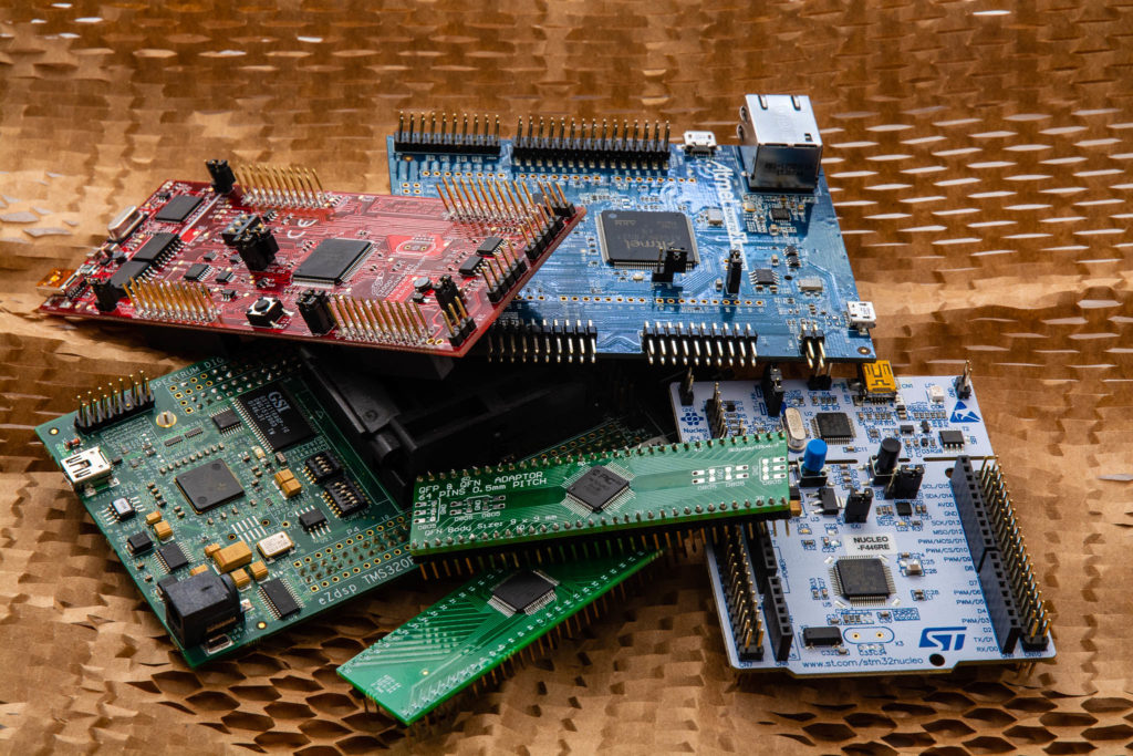
I chose a selection of MCUs that I have experience using, have the tools to develop, and cover a range of core types.  The price varies greatly between the most expensive and least expensive MCU I tested.  The exact part chosen depended more on availability of development boards than any particular application requirement.  However, the overall family of each MCU has a variety of parts that cover a large range of price points and feature-sets.  That said, following are the MCUs:

Continue reading

BLDC Skateboard Part 7

In Part 1, I determined what components were needed to turn the motor I found.

In Part 2, I determined what parts were needed to attach the motor to the skateboard wheel.

In Part 3, I created the mount and attached the motor to the skateboard.

In Part 4, I applied current to the motor to correctly label the wiring and hall effect sensors for use in a commutation table for trapezoidal control.

In Part 5, I set up the hardware and hall effect sensor connections.

In Part 6, I created the BLDC trapezoidal control firmware and made the motor spin.

In this part, I will cover setting up the CC110L boosterpacks on both the motor control launchpad and the MSP430 launchpad to create a wireless controller for the skateboard.  I will also discuss the analog input used for the controller.

When I started this project, I wanted to try to use some CC110L radios I had left over from a previous project.  These are sub-GHz transceivers that use an SPI interface to the MCU.  They plug directly into the launchpads I am using and are relatively inexpensive.

First, the links on the TI website that point to the Anaren site for more information on the CC110L boosterpack do not really work.  Here is the user manual for the CC110L boosterpack that I downloaded back when the links did work.  This contains the connector pinouts, jumper settings, and schematics that are missing otherwise.

Continue reading

BLDC Skateboard Part 6

In Part 1, I determined what components were needed to turn the motor I found.

In Part 2, I determined what parts were needed to attach the motor to the skateboard wheel.

In Part 3, I created the mount and attached the motor to the skateboard.

In Part 4, I applied current to the motor to correctly label the wiring and hall effect sensors for use in a commutation table for trapezoidal control.

In Part 5, I set up the hardware and hall effect sensor connections.

Now, we will go over the trapezoidal control firmware and finally spin the motor.  Before we begin, the C2000 series of MCUs from TI are quite powerful, but also quite complex.  I am going to skip over some of the setup complexity for brevity.  I recommend downloading C2000ware  from TI for code examples to get started.  Also, make sure to read the errata for the MCU (there is an ADC problem that must be worked around or else readings will be incorrect).  Furthermore, I am using a C2000 MCU for this project , however the basic foundation of what I cover will work with almost any MCU.

The trapezoidal control firmware contains two main loops: the main system loop that executes tasks that are not time sensitive and the control loop that must be executed timely.  I, generally, like to set up a CPU timer that interrupts every 1ms and increments various counter variables to be used in the main system loop for periodic events.  These periodic events could be communication to outside devices, LED blinks, or polling general I/O.  The other portion of the main system loop is a state machine that processes outside inputs and enables the PWMs appropriately.

Continue reading

BLDC Skateboard Part 5

In Part 1, I determined what components were needed to turn the motor I found.

In Part 2, I determined what parts were needed to attach the motor to the skateboard wheel.

In Part 3, I created the mount and attached the motor to the skateboard.

In Part 4, I applied current to the motor to correctly label the wiring and hall effect sensors for use in a commutation table for trapezoidal control.

Now we finally will set up our TMS320F28069 Launchpad and DRV8323 Boosterpack to spin the motor using trapezoidal control.  Before we begin, the C2000 series of MCUs from TI are quite powerful, but also quite complex.  I am going to skip over some of the setup complexity for brevity.  I recommend downloading C2000ware from TI for code examples to get started.  Furthermore, I am using a C2000 MCU for this project (I plan on covering much more complex control with it in future posts), however the basic foundation of what I cover will work with almost any MCU.

To get started, we need to connect the hall effect sensors to the DRV8323 boosterpack.  This particular boosterpack has a header specifically for hall effect sensors on J2.  The circuit already contains the pull-up resistors and lowpass filters we need to condition the signal:

Continue reading

BLDC Skateboard Part 4

In Part 1, I determined what components were needed to turn the motor I found.

In Part 2, I determined what parts were needed to attach the motor to the skateboard wheel.

In Part 3, I created the mount and attached the motor to the skateboard.

Now that the motor is mounted to the skateboard, we need to spin it at full speed to make sure everything is balanced and aligned.

The motor I am using has three hall effect sensors located 120 degrees apart from each other around the stator.   This is a typical setup for BLDC motors that have sensors.  The sensors detect the magnetic field of the permanent magnets in the rotor and can be used to both excite the motor phases to get the rotor turning and as a course method to determine rotor speed.  This is called trapezoidal control.

The motor actually has a detailed specification sheet, however most inexpensive brushless motors do not have anything like this.  To be thorough, we will use a current limited DC power supply to determine which sensors are active for each position of the rotor and check our findings with the specification sheet.  Then, we will make an appropriate commutation table to excite the motor phases.

Since most hall effect sensors have open collector outputs, we need to create a simple circuit on a breadboard to read the feedback from the sensors.  We will also use this circuit to power the hall effect sensors.

Continue reading

BLDC Skateboard Part 3

In Part 1, I determined what components were needed to turn the motor I found.

In Part2, I determined what parts were needed to attach the motor to the skateboard wheel.

The next step is attaching the motor to the skateboard and the installation of the pulleys and belts to the wheel.   First, I decided to attach the large pulley to the wheel.  Both pulleys I ordered are made from aluminum.  This makes everything corrosion resistant and relatively easy to work with since you can use common woodworking tools to form it.

The large pulley needed the center mounting hole enlarged to clear the axle.  This was easy with a drill press and 3/4 inch bit.  I also decided to trim off the mounting flange with a bandsaw.  I, then, drilled and tapped two holes in the pulley to accept some stainless 6-32 thread 2 inch long button head screws.  Finally, I drilled two holes in the wheels for the screws and threaded them through the wheels into the pulley.  The important part is making sure the pulley is completely centered before marking and drilling any holes.

Continue reading

BLDC Skateboard Part 2

In Part 1, I determined what components were needed to turn the motor I found.  Now I need to figure out how to make the motor turn the skateboard wheels.

The most straight-forward way to spin the wheel is to simply attach the skateboard wheel directly to the motor shaft.  However, I want to make sure I have enough torque available to get the board moving with me on it.  Thus, I plan on using either a belt or chain with sprockets on the motor shaft and attached to the inside of the wheel.  This will allow me to use gear reduction to gain some extra torque.

This brings up some more questions:

  • How much gear reduction is possible before the top speed of the skateboard is too low?
  • What top speed is possible to begin with and what is too fast?

Luckily, I have an old skateboard laying around to do some tests, a decent hill nearby, and a GPS to record my speed.  I discovered really quickly that 20 MPH is more than fast enough for me right now!

To determine the theoretical top speed of the motor and skateboard combination, we need to look at the motor specification sheet.  It says that the theoretical unloaded max speed of the motor is 5270 RPM.  We might be able to hit that going downhill, but my weight, friction, and air resistance will greatly reduce the speed the motor can attain under normal circumstances.

Continue reading

BLDC Skateboard Part 1

When you work with microcontrollers, you tend to accumulate all sorts of development boards that get used a few times and tossed in a pile in some drawer.  It seems so wasteful to just leave them sitting there, so I decided I should start a summer project to put a few to work.

Once I found an amazing deal on a small very high quality BLDC motor, I knew exactly what I needed to make: a motorized skateboard.

BLDC Motor

I pulled out the quite nice TI TMS320F28069 Launchpad, grabbed a DRV8323RS Boosterpack, a MSP430 Launchpad from my pile (they were $4.30 a few years ago!), and stole some old C110L boosterpacks from another project.  The idea is to use the TMS320F28069 and DRV8323 to spin the motor and the MSP430 as the wireless remote.

The TMS320F28069M has TI’s proprietary InstaSPIN code embedded in some ROM, but that is no fun.  I am going to evaluate a few different methods of controlling the motor and see what works best – if this motor even has enough torque or if the DRV8323 boosterpack’s 20A peak current is enough to get me and the skateboard moving.

If I like the way it performs, I might even design a custom board for it and use it to get around town.

The first problem to solve is how to attach the motor to the skateboard and wheels … we will figure that out in part 2.