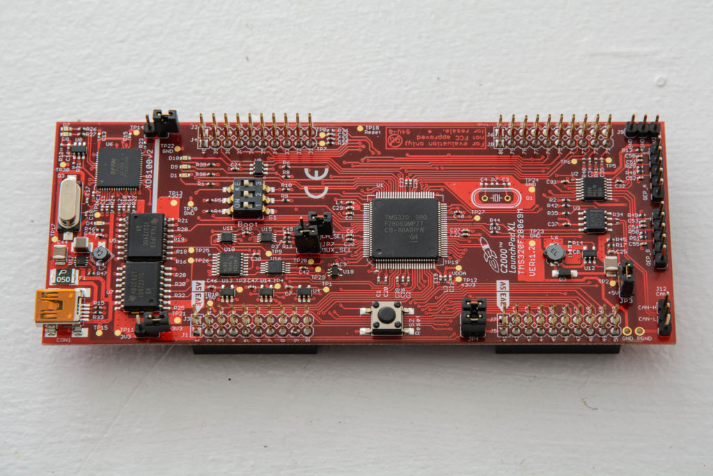
Startup without peripheral libraries series
The TI C2000 series of MCUs are not designed for people new to development. TI does not have any software that auto-configures the devices, the startup code does not automatically populate things like vectored interrupt tables, and register defaults require configuration. However, TI does provide an extensive set of generic hardware configuration files and peripheral example files for every peripheral that are clean and concise. I like this much better than any configuration utility. The best way to get started is to download C2000Ware.
I will be using some of the files from C2000Ware in this example:
- The headers for the MCU. Each has the filename: F2806x_ZZ.h, where ZZ is the peripheral the header defines. These are found the device_support/f2806x/headers/include directory in the C2000Ware installation directory. I like that these provide bit fields.
- The variable structure definition file: F2806x_GlobalVariableDefs.c. This is found in the device_support/f2806x/headers/source directory.
- The linker scripts: F2806x_Headers_nonBIOS.cmd (device_support/f2806x/headers/cmd) and F28069.cmd (device_support/f2806x/common/cmd)
Startup consists of the following (most of this is pulled straight out of the TI examples):
- Disable the watchdog – it can be enabled later and is turned on by default
- Set up the internal oscillator
- Initialize the PLL
- Start any needed peripheral clocks
- Set up the PIE and interrupt vector tables
- Set up the flash
- Initialize any needed peripherals
Please note, I stuck all this in one file to make it easier to view on the web. Normally, this would be set up as callable hardware libraries.
#include "F2806x_Device.h"
#include "F2806x_DefaultISR.h"


void systemInit (void)
{
   // Disable the watchdog
   EALLOW;
   SysCtrlRegs.WDCR = 0x0068;
   EDIS;

   //---------------------------------------------------------------
   // Set up the oscillator
   //---------------------------------------------------------------
   EALLOW;
   SysCtrlRegs.CLKCTL.bit.INTOSC1OFF = 0;
   SysCtrlRegs.CLKCTL.bit.OSCCLKSRCSEL=0; // Clk Src = INTOSC1
   SysCtrlRegs.CLKCTL.bit.XCLKINOFF=1; // Turn off XCLKIN
   SysCtrlRegs.CLKCTL.bit.XTALOSCOFF=1; // Turn off XTALOSC
   SysCtrlRegs.CLKCTL.bit.INTOSC2OFF=1; // Turn off INTOSC2

   // Low speed clock
   SysCtrlRegs.LOSPCP.bit.LSPCLK = 2; // SYSCLK/4
   EDIS;

   //---------------------------------------------------------------
   // Set up the PLL
   //---------------------------------------------------------------
   // Make sure the PLL is not running in limp mode
   if (SysCtrlRegs.PLLSTS.bit.MCLKSTS != 0)
   {
      EALLOW;
      // OSCCLKSRC1 failure detected. PLL running in limp mode.
      // Re-run missing clock logic.
      SysCtrlRegs.PLLSTS.bit.MCLKCLR = 1;
      EDIS;
      // Replace this line with a call to an appropriate
      // SystemShutdown(); function.
      __asm(" ESTOP0"); // Uncomment for debugging purposes
   }

   // DIVSEL MUST be 0 before PLLCR can be changed from
   // 0x0000. It is set to 0 by an external reset XRSn
   // This puts us in 1/4
   if (SysCtrlRegs.PLLSTS.bit.DIVSEL != 0)
   {
      EALLOW;
      SysCtrlRegs.PLLSTS.bit.DIVSEL = 0;
      EDIS;
   }

   EALLOW;

   //
   // Before setting PLLCR turn off missing clock detect logic
   //
   SysCtrlRegs.PLLSTS.bit.MCLKOFF = 1;
   SysCtrlRegs.PLLCR.bit.DIV = 18;
   EDIS;

   //
   // Wait for the PLL lock bit to be set.
   //

   while(SysCtrlRegs.PLLSTS.bit.PLLLOCKS != 1)
   {
      // wait for PLL
   }

   EALLOW;
   SysCtrlRegs.PLLSTS.bit.MCLKOFF = 0;
   EDIS;


   // Set the divider
   EALLOW;
   SysCtrlRegs.PLLSTS.bit.DIVSEL = 2;
   EDIS;

   //--------------------------------------------------------------
   // Periperhal clocks
   //--------------------------------------------------------------
   EALLOW;
   // low speed clock
   SysCtrlRegs.LOSPCP.all = 0x0002;

   //
   // XCLKOUT to SYSCLKOUT ratio. By default XCLKOUT = 1/4 SYSCLKOUT
   //
   SysCtrlRegs.XCLK.bit.XCLKOUTDIV=2;

   // Enabled clocks
   SysCtrlRegs.PCLKCR3.bit.CPUTIMER0ENCLK = 1; // CPU Timer 0
   EDIS;

   //---------------------------------------------------------------
   // PIE
   //---------------------------------------------------------------
   //
   // Disable Interrupts at the CPU level
   //
   DINT;

   //
   // Disable the PIE
   //
   PieCtrlRegs.PIECTRL.bit.ENPIE = 0;

   //
   // Clear all PIEIER registers
   //
   PieCtrlRegs.PIEIER1.all = 0;
   PieCtrlRegs.PIEIER2.all = 0;
   PieCtrlRegs.PIEIER3.all = 0;
   PieCtrlRegs.PIEIER4.all = 0;
   PieCtrlRegs.PIEIER5.all = 0;
   PieCtrlRegs.PIEIER6.all = 0;
   PieCtrlRegs.PIEIER7.all = 0;
   PieCtrlRegs.PIEIER8.all = 0;
   PieCtrlRegs.PIEIER9.all = 0;
   PieCtrlRegs.PIEIER10.all = 0;
   PieCtrlRegs.PIEIER11.all = 0;
   PieCtrlRegs.PIEIER12.all = 0;

   //
   // Clear all PIEIFR registers
   //
   PieCtrlRegs.PIEIFR1.all = 0;
   PieCtrlRegs.PIEIFR2.all = 0;
   PieCtrlRegs.PIEIFR3.all = 0;
   PieCtrlRegs.PIEIFR4.all = 0;
   PieCtrlRegs.PIEIFR5.all = 0;
   PieCtrlRegs.PIEIFR6.all = 0;
   PieCtrlRegs.PIEIFR7.all = 0;
   PieCtrlRegs.PIEIFR8.all = 0;
   PieCtrlRegs.PIEIFR9.all = 0;
   PieCtrlRegs.PIEIFR10.all = 0;
   PieCtrlRegs.PIEIFR11.all = 0;
   PieCtrlRegs.PIEIFR12.all = 0;

    //
   // Enable the PIE Vector Table
   //
   // The tables should really be set up with dummy functions, but this is just an example
   PieCtrlRegs.PIECTRL.bit.ENPIE = 1;

   //---------------------------------------------------------------
   // Flash init
   //---------------------------------------------------------------
   EALLOW;

   //
   // Enable Flash Pipeline mode to improve performance of code executed from
   // Flash.
   //
   FlashRegs.FOPT.bit.ENPIPE = 1;

   //
   // Set the Paged Waitstate for the Flash
   //
   FlashRegs.FBANKWAIT.bit.PAGEWAIT = 3;

   //
   // Set the Random Waitstate for the Flash
   //
   FlashRegs.FBANKWAIT.bit.RANDWAIT = 3;

   //
   // Set the Waitstate for the OTP
   //
   FlashRegs.FOTPWAIT.bit.OTPWAIT = 5;

   FlashRegs.FSTDBYWAIT.bit.STDBYWAIT = 0x01FF;
   FlashRegs.FACTIVEWAIT.bit.ACTIVEWAIT = 0x01FF;
   EDIS;

   //---------------------------------------------------------------
   // Timer 1 Init
   //---------------------------------------------------------------
   // Make sure timer is stopped
   CpuTimer0Regs.TCR.bit.TSS = 1;

   // Set timer interrupt callback function
   EALLOW;
   PieVectTable.TINT0 = &timer0_isr;
   EDIS;

   // Timer period - 1ms
   CpuTimer0Regs.PRD.all = 90000 - 1;

   // Initialize pre-scale counter to divide by 1 (SYSCLKOUT)
   CpuTimer0Regs.TPR.all = 0;
   CpuTimer0Regs.TPRH.all = 0;

   // Reload all counter register with period value, no free run
   CpuTimer0Regs.TCR.bit.TRB = 1;
   CpuTimer0Regs.TCR.bit.SOFT = 0;
   CpuTimer0Regs.TCR.bit.FREE = 0;

   // Enable timer interrupt
   CpuTimer0Regs.TCR.bit.TIE = 1;

   // Start Timer
   CpuTimer0Regs.TCR.bit.TSS = 0;

   // Enable CPU timer 0 int
   IER |= M_INT1;

   // Enable TINT0 in the PIE: Group 1 interrupt 7
   PieCtrlRegs.PIEIER1.bit.INTx7 = 1;
}
