My daughter has been using her highly modified power wheels style car for quite a while now and I decided that a few issues needed to be fixed:
- Running the motors in parallel means that one motor could be damaged by using a majority of current in certain situations
- It is too easy to make the driven wheels spin out on wet surfaces or when trying to go over obstacles
- My wife thinks the car is much too fast at times and needs to be slowed down
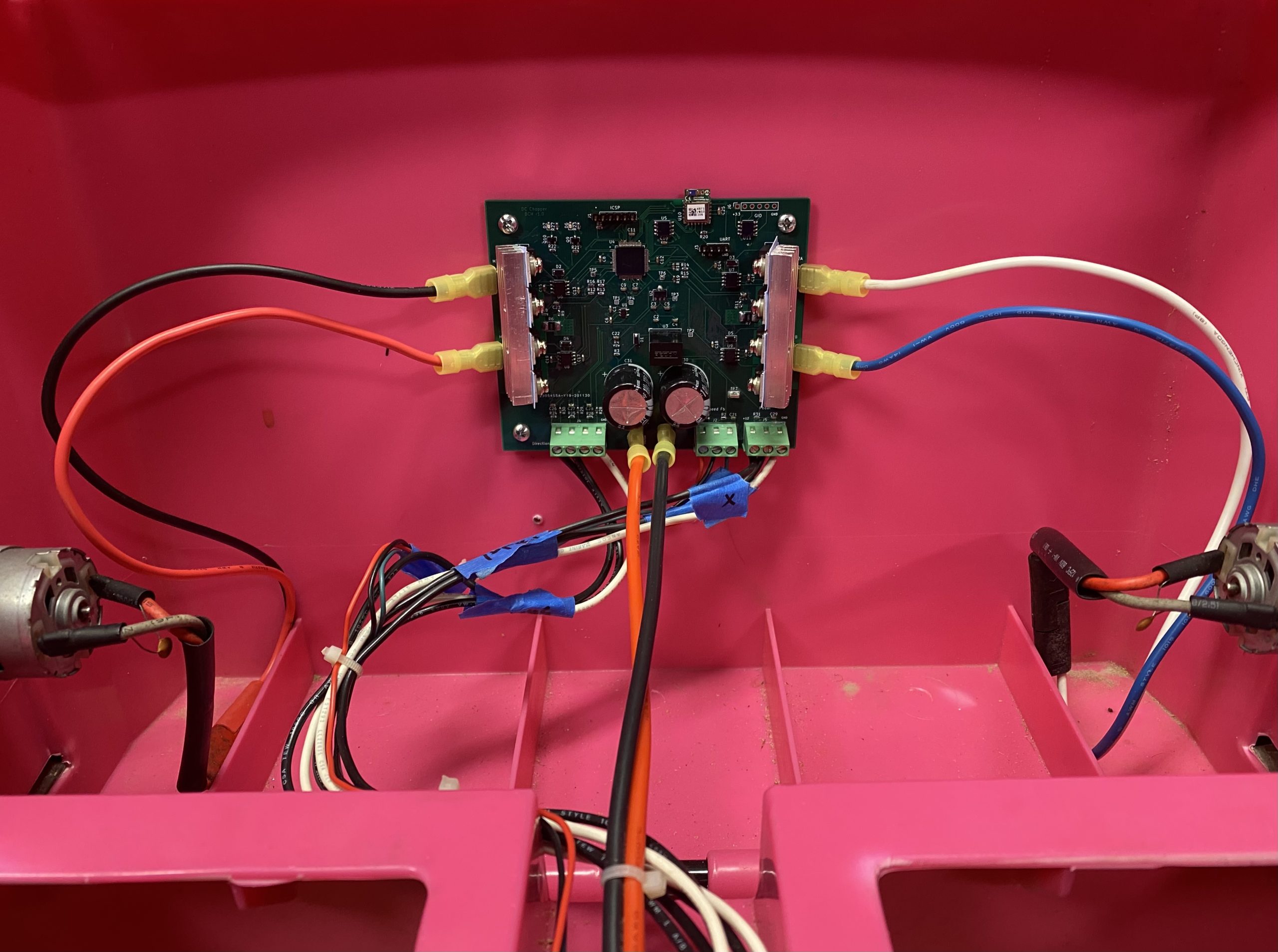
New Control Board
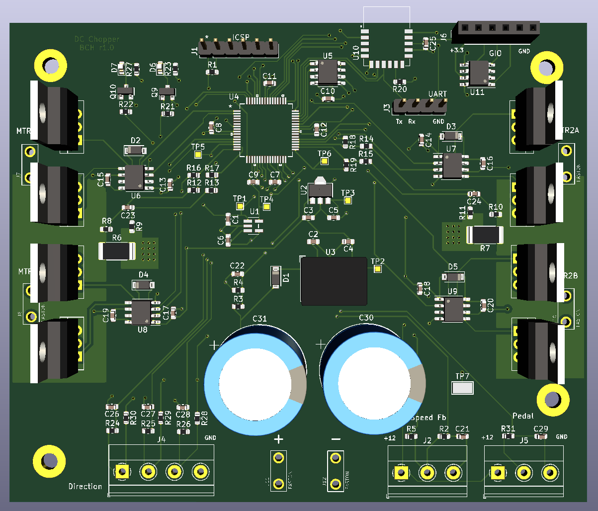
I designed a new control board to independently control each motor. This allows me to finely control the speed and torque of each motor separately.
For fun, I designed the board to use a dsPIC33CK256MP506. It has great ADC and PWM implementations, plus onboard op-amps to cut back on BOM requirements. However, this is a fixed point MCU, so I had to re-write a good portion of my control code. I appreciated this challenge as it provided me a good refresher on fixed-point math. I have received a few questions about fixed point control code in comments on other posts and will go over some of it later on in this post.
Front Wheel Speed Sensor
Part of the new control board implementation was to allow for a front wheel speed sensor.
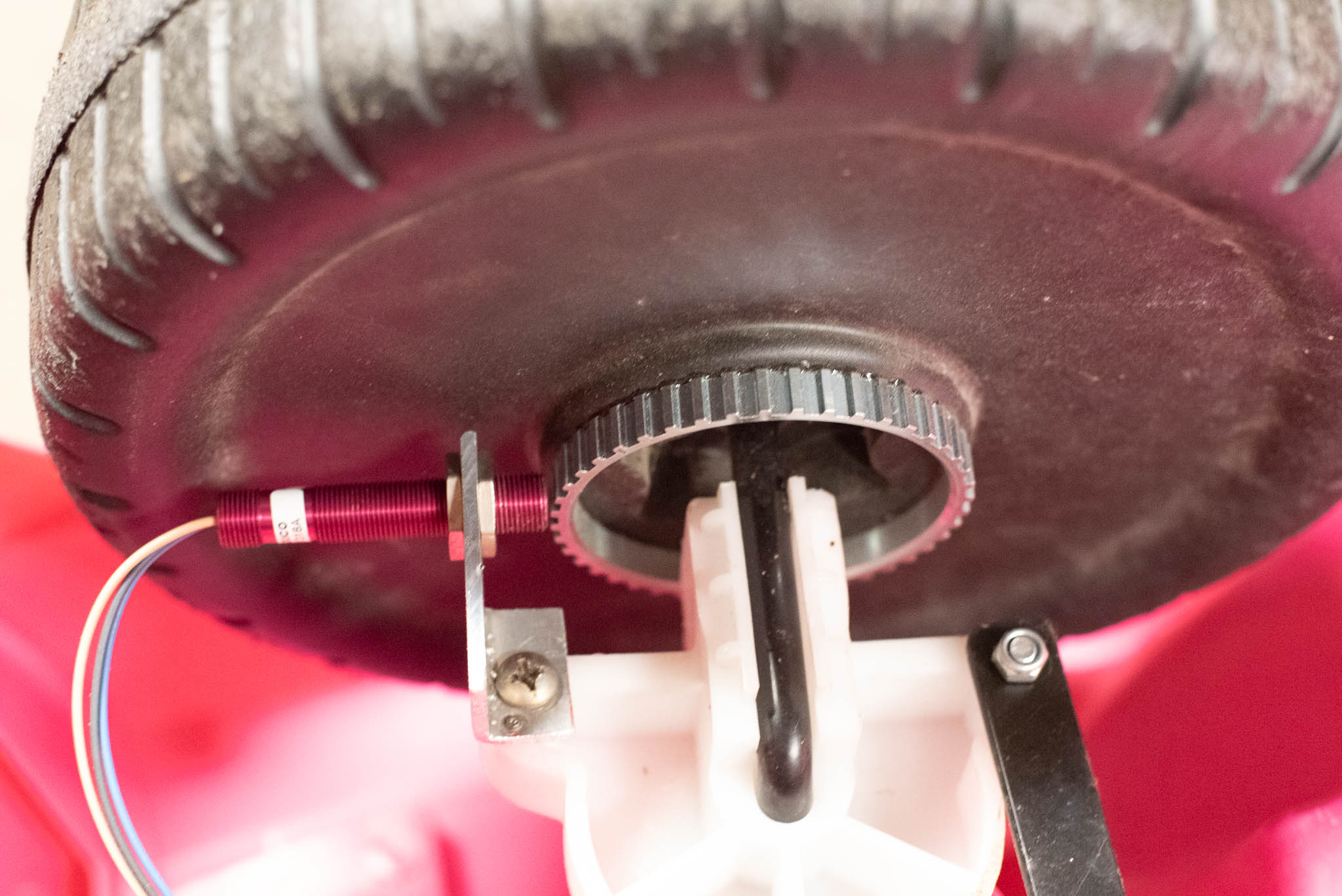
The front wheel speed sensor provides an undriven feedback that gives an accurate representation of car speed in order to limit the max speed and also to provide a reference for rear (driven) wheel slip. The sensor I chose is a hall effect type that must be placed near a toothed wheel. Each tooth causes the sensor to output a pulse (really, the sensor is open collector, so each tooth causes the sensor to pull the signal line down to ground). I chose an automotive ABS tone wheel as the toothed wheel as this style of sensor is used for the ABS and traction control systems in most automobiles. An ABS tone wheel is inexpensive and easy to find.
The QEP peripheral of the dsPIC allows me to both count the pulses from the wheel over time and time each individual pulse. I can switch between these methods depending on wheel speed for the most accurate speed calculation. This speed is this used in an outer speed PI loop that limits current as the speed reaches a max threshold. This is preferable to simply limiting duty cycle as it allows full current as long as the car is below the max threshold. That means the car can still climb steep hills in speed limited mode.
The “shifter” in the car has three positions. The middle position is configured to use the speed PI loop to limit the max speed regardless of pedal position. The farthest forward position bypasses the speed PI loop and runs the car as fast as the driver wants. The backmost position is reverse and is speed limited.
Traction Control
To implement traction control, the system must both measure car speed (using the front wheel speed sensor) and rear driven wheel speed.
Rear wheel speed can be coarsely determined using a simple DC motor equation:
speed = (motorVoltage - (motorCurrent * motorResistance)) / Ke
motorVoltage is the voltage being applied to the motor. Roughly, this can be assumed to be the battery voltage multiplied by the duty cycle. For example, an 18 volt battery at 50% duty cycle would be applying 9 volts to the motor. motorCurrent is measured every cycle for the control loop. motorResistance can be obtained from the motor specifications, or in my case, by carefully measuring the resistance across the motor leads from a few different rotor positions. When doing this, make sure you use a high resolution meter and compensate for the resistance of the meter leads. Finally, Ke can be obtained from the motor specifications or calculated by running the motor at rated voltage, measuring the speed, and dividing the rated voltage by the speed.
In my case, I wanted to compare front wheel speed to rear wheel speed, so I measured the rear wheel speed instead of the motor speed. This takes the gear reduction into account. Whatever unit of speed you use for the measurement is what the equation will output. The Ke speed component is generally specified in Radians per Second (rad/s) or Rotations per Minute (RPM).
Once the front wheel speed is measured and the rear wheel speed is calculated, the system calculates the percent difference between those speeds. That percent difference is the slip percent. The optimal slip percent varies depending on conditions, but it is always greater than 0%. I found around 12% to work pretty well and still be fun to drive. Spinning the wheels of the car is fun, but 12% lets it actually get moving after some spinning.
The beauty of controlling each motor separately is that this gives us a limited slip style differential for free. A single wheel never spins more than 15% more than the front wheel even if it is in the air. Following is a video that shows the impact of traction control on the car (it is being driven using bluetooth):
Fixed Point PI Regulator Implementation
How is the control applied in fixed point? First, an overview of the control system is required (duplicated per motor):
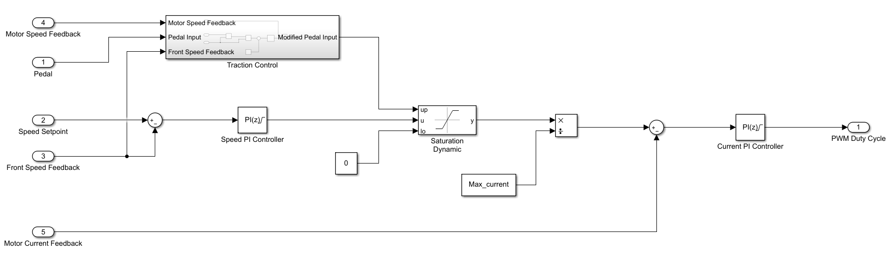
The speed PI loop follows the traction control logic. The output of the speed PI is a current command. The traction control logic modifies the torque command that clamps the speed PI. That command is compared to the motor current feedback and input into a current PI loop. The output of the current PI loop is the duty cycle for the PWM to output.
The PI regulators in the system use the built-in DSP functions of the dsPIC. These are not standard C instructions and use special functions defined by the compiler.
The proportional gains are defined as “Q11” numbers. This means the gain is multiplied by 2^11 before being used in the calculation. This gives an effective resolution of 15.9995 to -16. The rest of the values are stored in “Q15” numbers and are multiplied by 2^15. This gives an effective resolution of 0.99997 to -1.
Following is the fixed point PI code:
typedef struct
{
   int16_t Kp;       // Q11, 15.9995 to -16
   int16_t Ki;       // Q15, 0.99997 to -1
   int16_t error;    // Q15
   int16_t Ui;       // Q15
   int16_t clampMin; // Q15
   int16_t clampMax; // Q15
   int16_t output;   // Q15
} ctrlPiReg;

volatile register int16_t aReg asm("A");
volatile register int16_t bReg asm("B");

void ctrlPiRegUpdate(ctrlPiReg *pireg)
{
// Grab the Ui and shove it in the 'A' accumulator
aReg = __builtin_lac(pireg->Ui, 0);
// Use the built in MAC to compute the integral output
aReg = __builtin_mac(aReg, pireg->Ki, pireg->error, 0, 0, 0, 0, 0, 0, 0, 0);

// We are using a Q11 multiplier for the Kp to allow a larger
// value. This gets us a Q26 number when we multiply so we left
// shift it 4 bits to scale the value to Q30 as the DSP expects
bReg = __builtin_mpy(pireg->error, pireg->Kp, 0, 0, 0, 0, 0, 0);
bReg = __builtin_sftac(bReg, -4);
// Add the Ui and Up. Do it in the accumulator saturation
bReg = __builtin_addab(aReg, bReg);

// Pull the values out of the accumulators, scale, and round them
// using the system round setting (convergent)
pireg->Ui = __builtin_sacr(aReg, 0);
pireg->output = __builtin_sacr(bReg, 0);

// Saturate the output
if (pireg->output > pireg->clampMax)
{
    pireg->output = pireg->clampMax;
}
else if (pireg->output < pireg->clampMin)
{
    pireg->output = pireg->clampMin;
}

// Saturate the Ui
if (pireg->Ui > pireg->clampMax)
{
   pireg->Ui = pireg->clampMax;
}
else if (pireg->Ui < pireg->clampMin)
{
   pireg->Ui = pireg->clampMin;
}
}
The basic idea is that since the “A” and “B” accumulators are 40-bit, we do the multiplication in them because the result of multiplying two 16 bit numbers can be larger than 16 bits. The dsPIC can do this accumulator math in a single cycle. Any math that is done on numbers that are not “Q15”, must be compensated by shifting. For example, the proportional gain is Q11, so we shift the result of multiplication with it left 4 bits.
If your MCU does not have a 40-bit accumulator or similar, the results of multiplication must be stored in a 32-bit variable and shifted back into the correct “Q” number. Remember how C applies math operations and cast variables to 32-bit as needed.
The inputs to the PI regulators are normalized Q15 numbers. This means the current feedback in the current PI is scaled to the max value the hardware is configured to send the ADC before saturation (35A). The speed feedback is scaled to a large value that I anticipate the car never reaching (500 RPM). For example, a current value of 10A would then be 10A / 35A * 2^15. The divide does not actually have to happen because the hardware is scaled such that a 12-bit ADC value of 4095 equals 35A. The ADC value then simply needs to be shifted left 4 bits and it is automatically normalized to 35A.