In Part 1, I determined what components were needed to turn the motor I found.
In Part 2, I determined what parts were needed to attach the motor to the skateboard wheel.
In Part 3, I created the mount and attached the motor to the skateboard.
In Part 4, I applied current to the motor to correctly label the wiring and hall effect sensors for use in a commutation table for trapezoidal control.
In Part 5, I set up the hardware and hall effect sensor connections.
Now, we will go over the trapezoidal control firmware and finally spin the motor. Before we begin, the C2000 series of MCUs from TI are quite powerful, but also quite complex. I am going to skip over some of the setup complexity for brevity. I recommend downloading C2000ware from TI for code examples to get started. Also, make sure to read the errata for the MCU (there is an ADC problem that must be worked around or else readings will be incorrect). Furthermore, I am using a C2000 MCU for this project , however the basic foundation of what I cover will work with almost any MCU.
The trapezoidal control firmware contains two main loops: the main system loop that executes tasks that are not time sensitive and the control loop that must be executed timely. I, generally, like to set up a CPU timer that interrupts every 1ms and increments various counter variables to be used in the main system loop for periodic events. These periodic events could be communication to outside devices, LED blinks, or polling general I/O. The other portion of the main system loop is a state machine that processes outside inputs and enables the PWMs appropriately.
The control loop executes based on the state of the PWM and execution of the ADC. When the PWM reaches the middle of a pulse, it triggers the ADC start of conversion interrupt. Once the ADC conversion is finished, it triggers an end of conversion interrupt. This interrupt grabs, valuates the results, and then runs the motor control loop. The control loop then updates the PWM duty cycle at the completion of execution.

I decided to use a control loop that consists of a speed regulator and current regulator. This gives me the ability to limit both the speed and current for testing with my bench-top power supply. The speed command will come from the potentiometer on the DRV8323 boosterpack board.

Rotor angle detection is the output of the hall effect sensors. This will be queried every control cycle (this is plenty fast enough to detect every hall effect pulse unless the motor spins more than 20k RPM and acts as a natural debounce for any noise on the sensors).
The speed calculation uses the ECAP peripheral of the TMS320F28069 MCU by incrementing a timer between each rising edge of the ‘A’ hall effect sensor. When a rising edge is detected, the timer starts and increments until the next rising edge. At the next rising edge, an ECAP interrupt routine is executed that calculates motor speed based on the timer value, the frequency of the timer, the pole pairs of the motor, and the state of the other hall effect sensors. If sensor ‘B’ is high when ‘A’ has a rising edge, the motor is turning forwards (positive speed). If sensor ‘C’ is high when ‘A’ has a rising edge, the motor is turning backwards (negative speed). If the capture timer overflows, I set the motor speed to zero. This is a very course way to measure speed, but is effective for what I am trying to accomplish and fits within the constraints of the development boards I am using.
The speed control portion of the firmware is a little more detailed than the simplified diagram above shows:
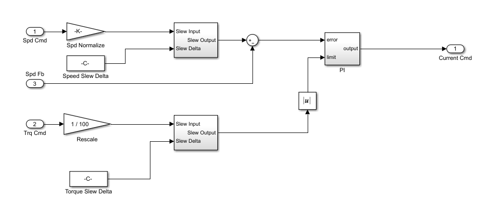
The speed and torque commands are normalized to a value between -1 and 1 and ramped at configurable rates. This keeps the system from applying current to the motor faster than we want. The torque command acts as a limit on the PI regulator output and integrator. It effectively is a current limit. The output of the speed PI regulator is a current command.
The current PI regulator uses the speed PI regulator output and measured current to output a duty cycle to the PWM.
In my firmware, I like to normalize all controlled variables to values between 1 and -1 when using floating point and max and min Q15 when using 16 bit fixed point. TI has a proprietary fixed point library, called IQ Math, that works with 32 bit ‘IQ’ numbers, but that is beyond the scope of this document. (I plan on writing a blog post in the future describing the normalization process in more detail)
Normalization allows system tuning and gains to stay fairly constant regardless of the size of motor and drive and makes comparison between plants of different sizes much easier.
Once the current regulator has output a duty cycle, we use the commutation table to determine which gates to turn on. I set up my commutation table as a lookup table based on the decimal value of the hall effect sensor feedbacks.
HA = 1, HB = 0, and HC = 0 is binary 0b100, which is equal to decimal 4. This will match a number that turns on the top A gate and bottom B gate in my PWM update routine:
uint16_t comTableFwd[] = { 0xF, 5, 3, 4, 1, 6, 2 };
uint16_t comTableRev[] = { 0xF, 2, 6, 1, 4, 3, 5 };
So, I grab the hall effect outputs:
hallOut = GpioDataRegs.GPADAT.bit.GPIO19 << 2;
hallOut+= GpioDataRegs.GPBDAT.bit.GPIO44 << 1;
hallOut+= GpioDataRegs.GPBDAT.bit.GPIO50;
Then, I set the commutation number to the lookup table value:
cmtnNum = comTableFwd[hallOut];
If the output of the speed PI is negative, I use the reverse lookup table instead of the forward lookup table shown above.
If the value from the commutation table is ‘0xF’, I stop the motor. This means one of the hall effect sensors is not working properly.
I then call the PWM update routine with the commutation number and duty cycle:
pwmUpdateTzoid(cmtnNum, piRegCur.output);
Following is a section of the PWM update routine. When ‘cmtnNum’ is equal to one, PWM1A is switched at the calculated duty cycle, PWM1B is forced off, PWM2A is forced off, PWM2B is forced on, and all of PWM3 is forced off. This allows current to flow from phase A to B:
void pwmUpdateTzoid (uint16_t cmtnNum, float dutyCycle)
{
    uint16_t period = ((float)PWM_PRD_TZOID * dutyCycle);
    // Fire the ADC at the center of the pulse
    EPwm1Regs.CMPB = period >> 1;

    // current flows from A to B
    if (cmtnNum == 1)
    {
        EPwm1Regs.AQCTLA.bit.ZRO   = AQ_SET;
        EPwm1Regs.AQCTLA.bit.CAU   = AQ_CLEAR;
        EPwm1Regs.CMPA.half.CMPA   = period;

        EPwm1Regs.AQCSFRC.bit.CSFA = 0;
        EPwm1Regs.AQCSFRC.bit.CSFB = 1;

        EPwm2Regs.AQCSFRC.bit.CSFA = 1;
        EPwm2Regs.AQCSFRC.bit.CSFB = 2;

        EPwm3Regs.AQCSFRC.bit.CSFA = 1;
        EPwm3Regs.AQCSFRC.bit.CSFB = 1;
    }

    // current flows from A to C
    else if (cmtnNum == 2)
    {
        EPwm1Regs.AQCTLA.bit.ZRO   = AQ_SET;
        EPwm1Regs.AQCTLA.bit.CAU   = AQ_CLEAR;
        EPwm1Regs.CMPA.half.CMPA   = period;

        EPwm1Regs.AQCSFRC.bit.CSFA = 0;
        EPwm1Regs.AQCSFRC.bit.CSFB = 1;

        EPwm2Regs.AQCSFRC.bit.CSFA = 1;
        EPwm2Regs.AQCSFRC.bit.CSFB = 1;

        EPwm3Regs.AQCSFRC.bit.CSFA = 1;
        EPwm3Regs.AQCSFRC.bit.CSFB = 2;
    }
Now, we program the MCU and spin the motor!
In the next part, we will create the MSP430 wireless remote control.